Identificación de ejes AxleTech, Meritor y Rockwell: cómo distinguirlos
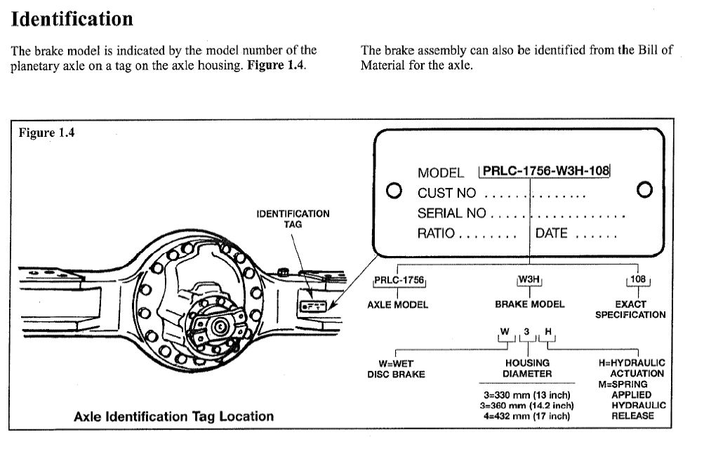
AxleTech fue separada de la división todoterreno de Rockwell International en 2002. Estos ejes se utilizan en diversas aplicaciones, como carretillas elevadoras, equipos de apoyo en tierra, grúas, elevadores aéreos y otros equipos todoterreno. Los ejes fabricados antes de 2002 llevaban la marca Rockwell. Los ejes fabricados a partir de 2002 llevaban la marca AxleTech. […]
Read Post